Loidatec Thermal Silicon carbide · MoSi2 · Passage Bricks · Contact straps and clamps
Products

Specifications, line by line.

Ranges below are what we hold in standard production. Anything inside them can be adjusted on the drawing — length, taper, thread, plating, packaging. Outside them, ask first and we will say whether it can be made.

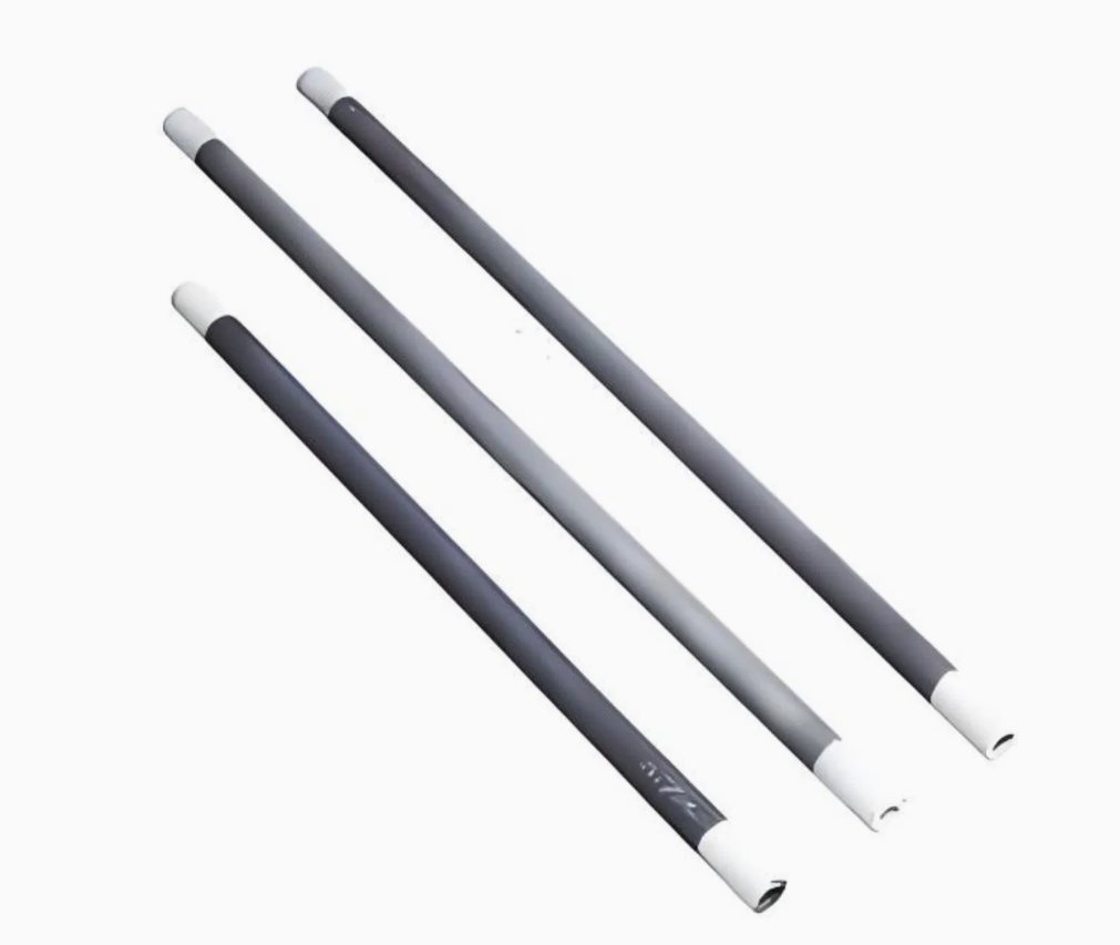
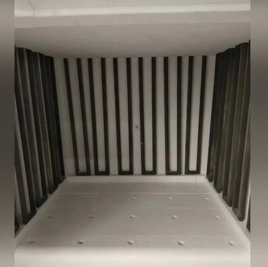
Silicon carbide heating elements in ED, U, W, L and spiral shapes Silicon carbide rods with threaded terminal ends SiC elements mounted in a furnace chamber
SiC · recrystallised
1 / 3

Silicon carbide heating elements

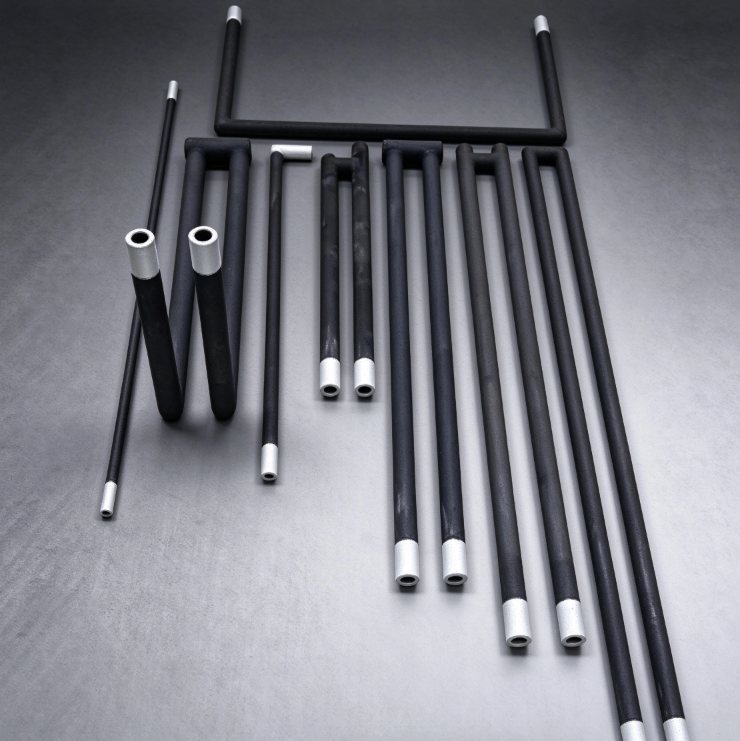
Recrystallised SiC elements for kilns, muffle furnaces and melting units. Supplied as equal-diameter (ED) rods, or bent into U, W and L shapes where the furnace layout needs the terminals out of the hot zone.

Typical specification
Element typesED, U, W, L, spiral, threaded terminal
Service temperature1400 °C continuous in air; up to 1500 °C intermittent
Hot zone diameter8 – 54 mm
Hot zone length100 – 2500 mm
Terminal length60 – 400 mm, equal or tapered
Resistance, cold1.2 – 8 Ω per element
Surface load5 – 8 W/cm² continuous
MaterialRecrystallised α-SiC, self-bonded
Threaded endsSlot terminalsAluminised coatingMatched setsSpare-set packing

SiC resistance rises with service time, typically 5–10% per 1000 hours at rated load. Replacement sets are quoted to the resistance of the elements being taken out, not to nominal.
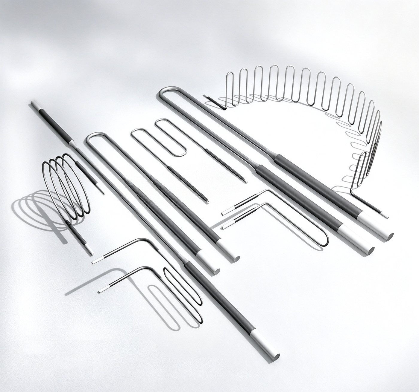
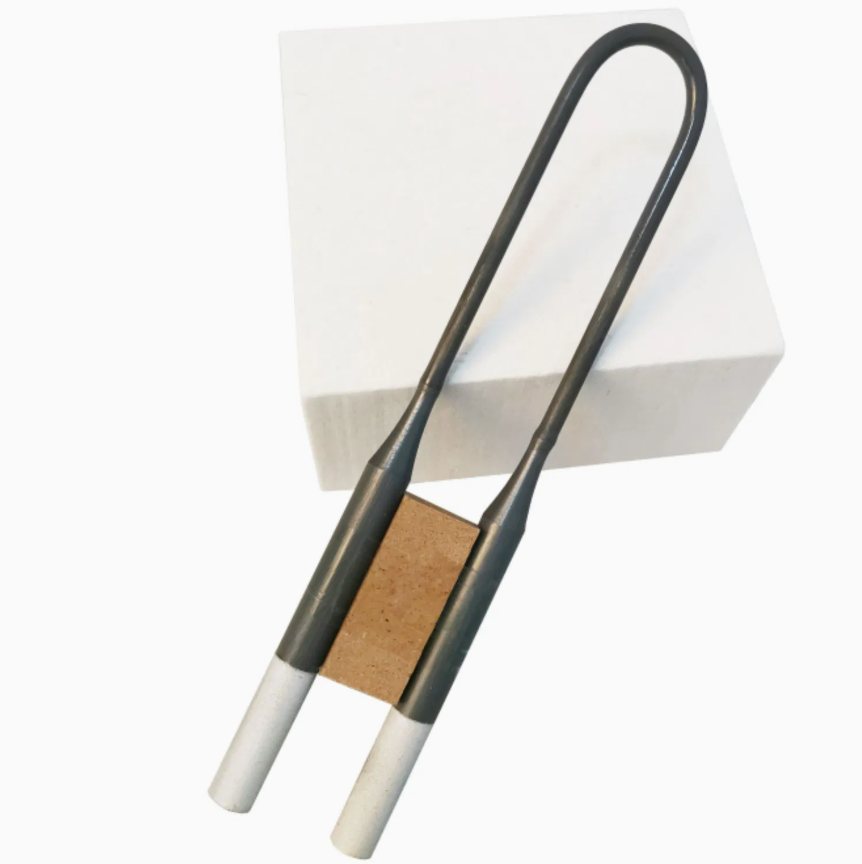
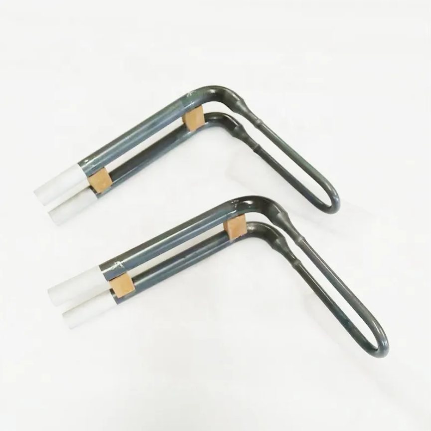
MoSi2 heating elements in U, W, L and spiral shapes MoSi2 U element with graded cold ends and holder block MoSi2 W element with ceramic terminal caps
MoSi2 · graded cold ends
1 / 3

MoSi2 heating elements

Molybdenum disilicide elements for the top of the temperature range. The cold ends are thicker than the hot zone and carry a lower surface load, so the terminal sits in the wall rather than in the heat.

Typical specification
Element typesU (170 / 180), W, L, straight rod
Service temperature1700 °C standard; 1800 °C high-grade, in air
Hot zone diameter3, 6, 9, 12 mm
Cold end diameter6, 9, 12, 18 mm (graded)
Hot zone length100 – 2000 mm
Shank length150 – 500 mm
Surface load1.4 – 2.0 W/cm² in continuous operation
Density5.5 – 5.9 g/cm³
170D / 180D typesCustom bend radiusCeramic terminal capsMatched sets

MoSi2 must be brought up through 400 °C quickly in air. Holding a new element in that band causes low-temperature oxidation (pesting) and shortens its life. Atmosphere limits are set out on the Technical page.

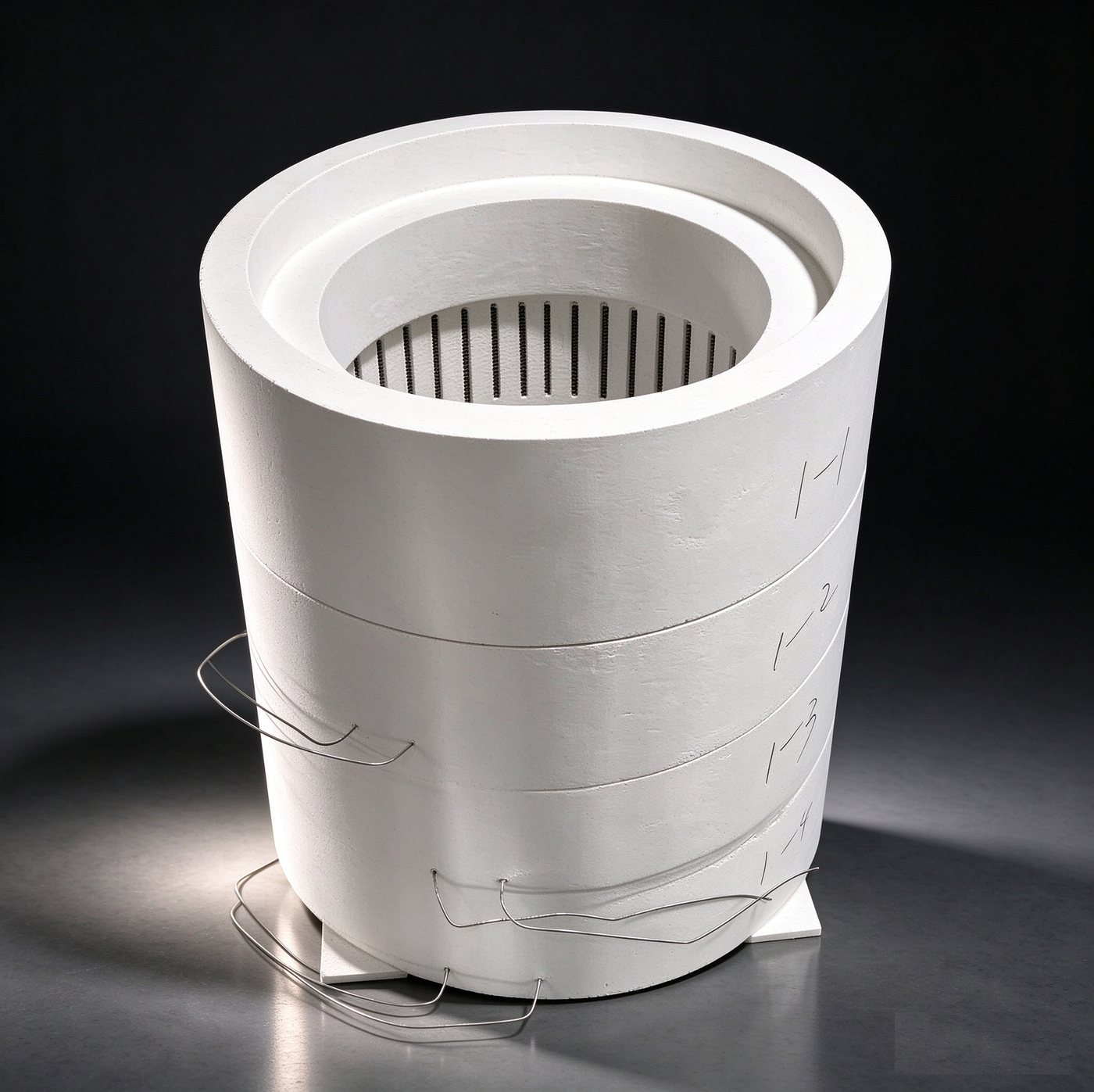
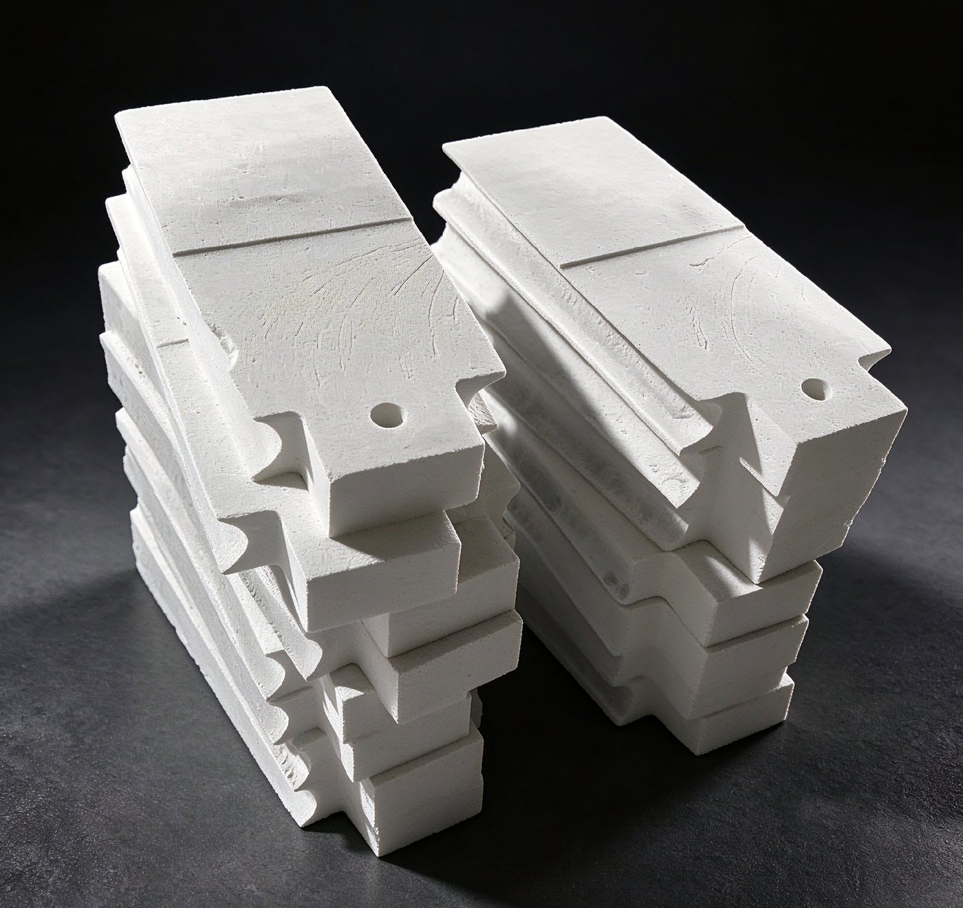
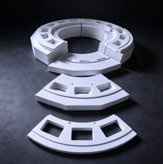
Passage brick assembly with element passages Stacked passage bricks, drilled and profiled to drawing Single passage brick with keyhole passage
Passage brick · Al2O3 65–90%
1 / 3

Passage bricks

A passage brick is the shaped block that lets a heating element pass through the furnace wall, roof or baffle. The block is pressed with one or more through-passages — round, oval or keyhole — at the spacing your element layout already uses, so the element is held at the right height, kept clear of the shell, and the opening stays closed against the furnace atmosphere.

Where the passage replaces a plain wall opening, the brick also carries the element's weight and takes the heat that conducts back through the wall. We make them in high-alumina and mullite-corundum grades, in single-passage, multi-passage and stepped blocks, cut and profiled to drawing, including the outer shape where it has to key into brickwork that is already in place.

Typical specification
FormsSingle-passage, multi-passage, stepped block, baffle plate
MaterialHigh-alumina and mullite-corundum; Al2O3 65 – 90%
Service temperature1400 °C continuous; 1550 – 1600 °C for corundum grades
Passage sectionRound, oval, rectangular, keyhole
Passage size8 – 60 mm diameter, or equivalent section
Block thickness40 – 200 mm
Block sizeTo drawing; typically up to 400 × 300 mm
Density2.3 – 3.0 g/cm³
Single passageMulti-passageStepped profileKeyhole sectionCut to drawing

Passage size is set by the element diameter at the wall plus clearance for thermal expansion — a passage cut to the nominal diameter will grip the element once the furnace is hot. Give us the element diameter, the wall thickness and the spacing, and the block and passage are sized on the drawing.

Braided copper contact straps and element clamps Bolted clamp with ceramic holder blocks Element clamped at both ends in a test rig
Contact straps · braided copper
1 / 3

Contact straps and clamps

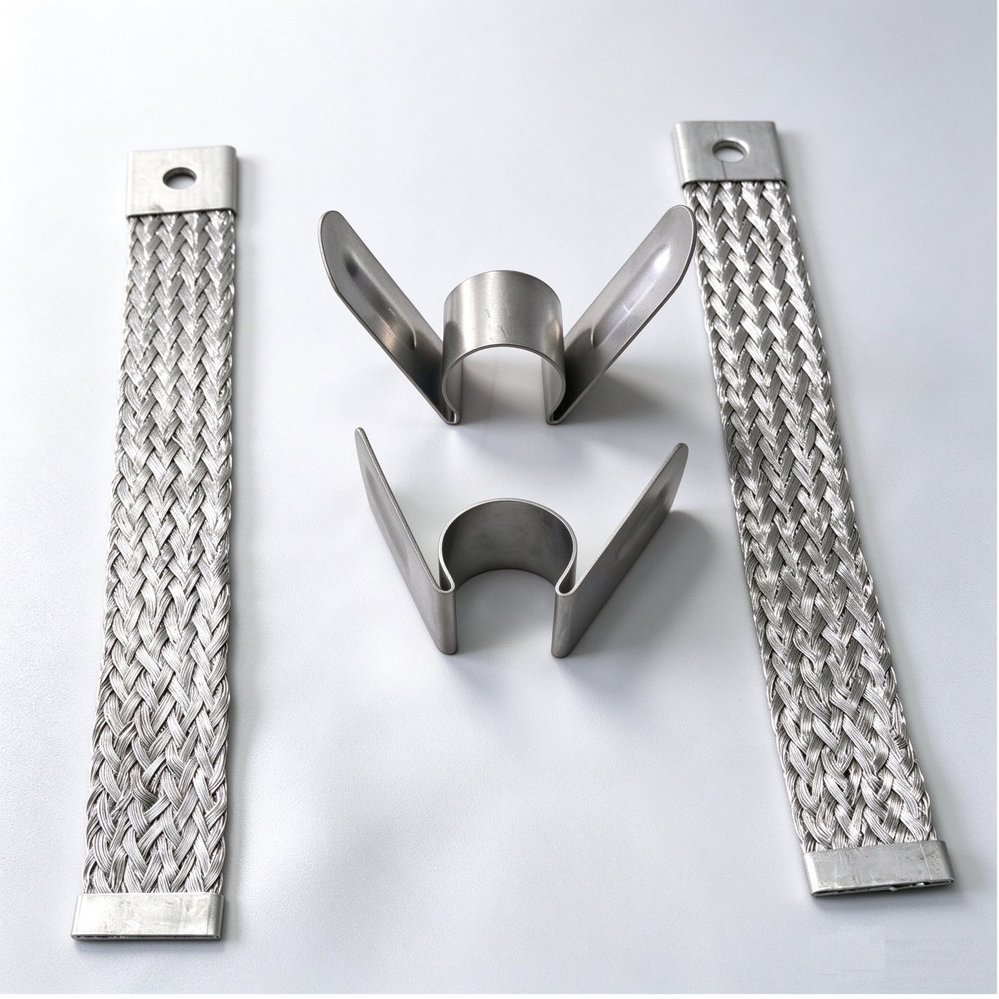
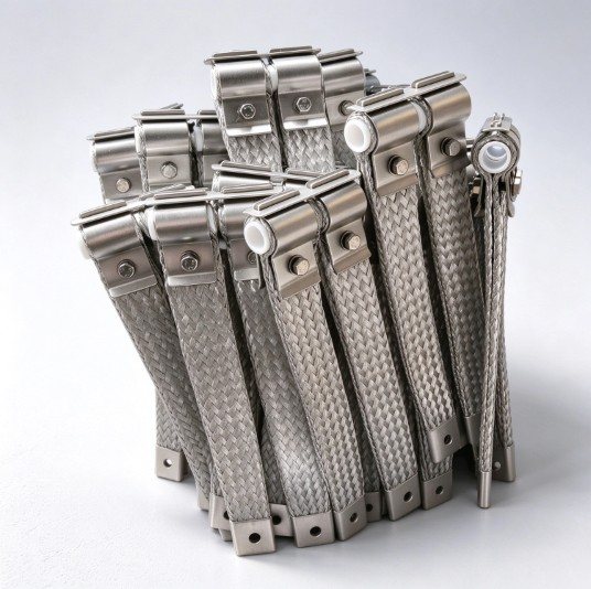
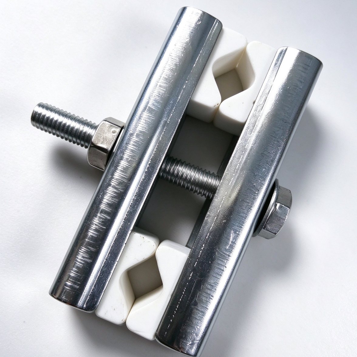
An element rarely fails at the terminal because the furnace was too hot. It fails because the joint worked loose. The strap, the clamp and the holder block together make the connection between the element shank and the busbar: flexible enough to absorb the element's thermal movement, tight enough to carry the current without heating at the contact.

We supply strap, clamp and ceramic holder as one matched set, sized to the shank you are connecting — round or flat, 10 to 60 mm — and tin-plated where the joint runs hot. The braid is cut to the length that clears the terminal box, with the lug or bolt hole already in place.

Typical specification
FormsBraided strap, bolted clamp, spring clamp, ceramic holder block
Strap materialTinned copper braid, Cu-ETP; aluminium on request
Strap width10 – 60 mm, single or multi-layer
Strap length100 – 1000 mm, cut to drawing
ClampStainless steel or galvanised, bolted M6 – M12
Shank range10 – 60 mm diameter, or flat section
Holder block95% Al2O3 ceramic, service to 1200 °C
PlatingTin 5 – 15 µm, matte or bright
Matched setsHeat-shrink sleeveBolt and washerPolarity markingBundle packing

Contact resistance is set by the clamp force and the condition of the two faces, not by the cross-section of the strap. Tell us the shank diameter, the busbar thickness and how the joint is made, and the clamp and strap are sized on the drawing.